Using white light interferometry system to detect multi-groove roughness plate
This time, the CR-100V white light interferometer is used, equipped with our independently developed 10X Linnik objective.
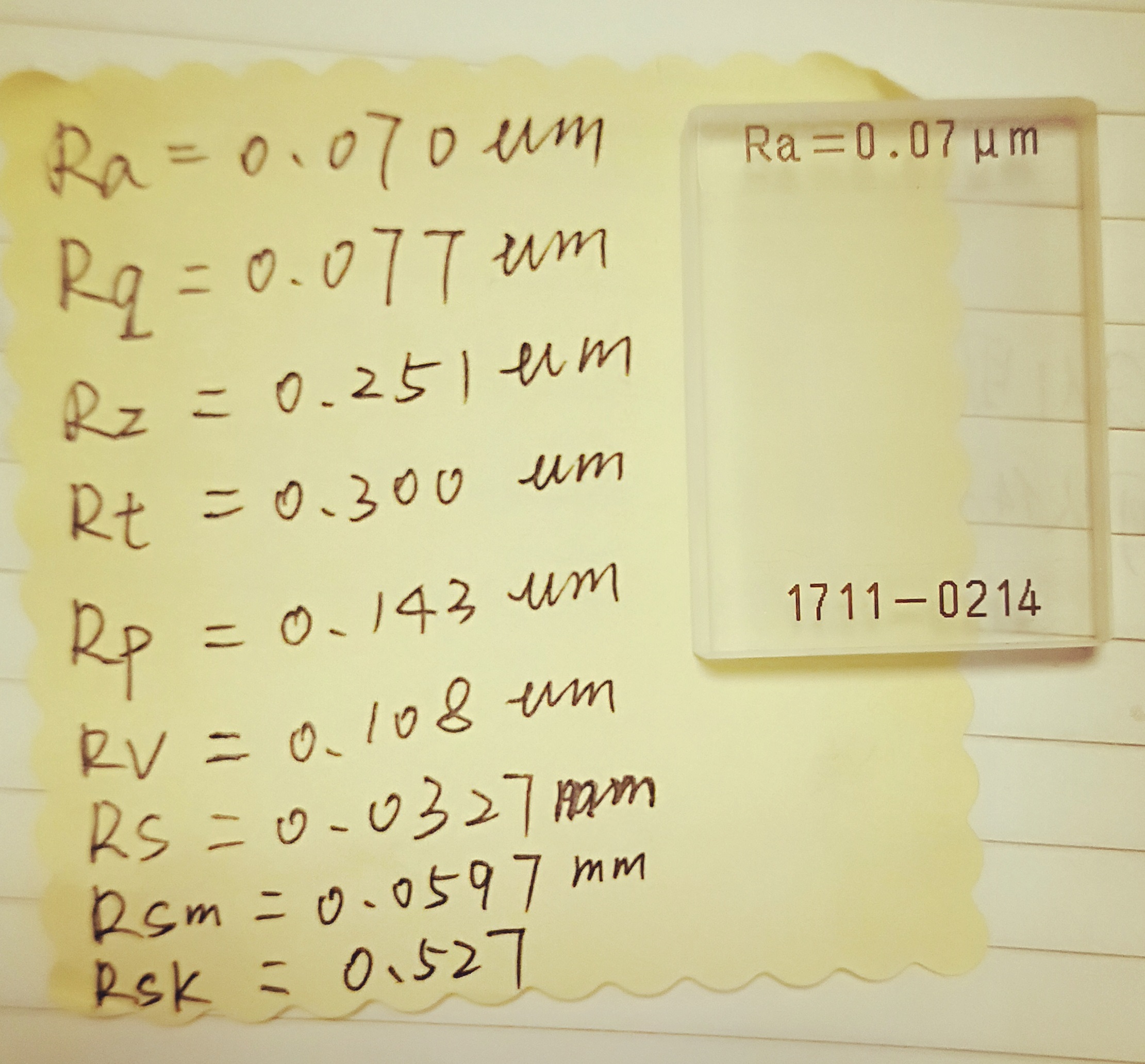
The multi-groove plate is generally used as a standard样板 for roughness testers. The multi-groove plate used is shown in the figure, and the left side shows the various parameter results measured by the roughness tester.
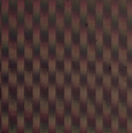
Multi-groove glass plate
According to the results measured by the roughness tester (unit: um):
Ra=0.07,Rq=0.077,Rp=0.143,Rv=0.108,Rz=0.251.
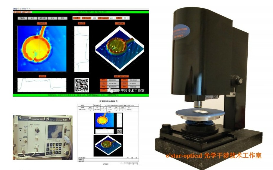
CR-100V white light interferometry system
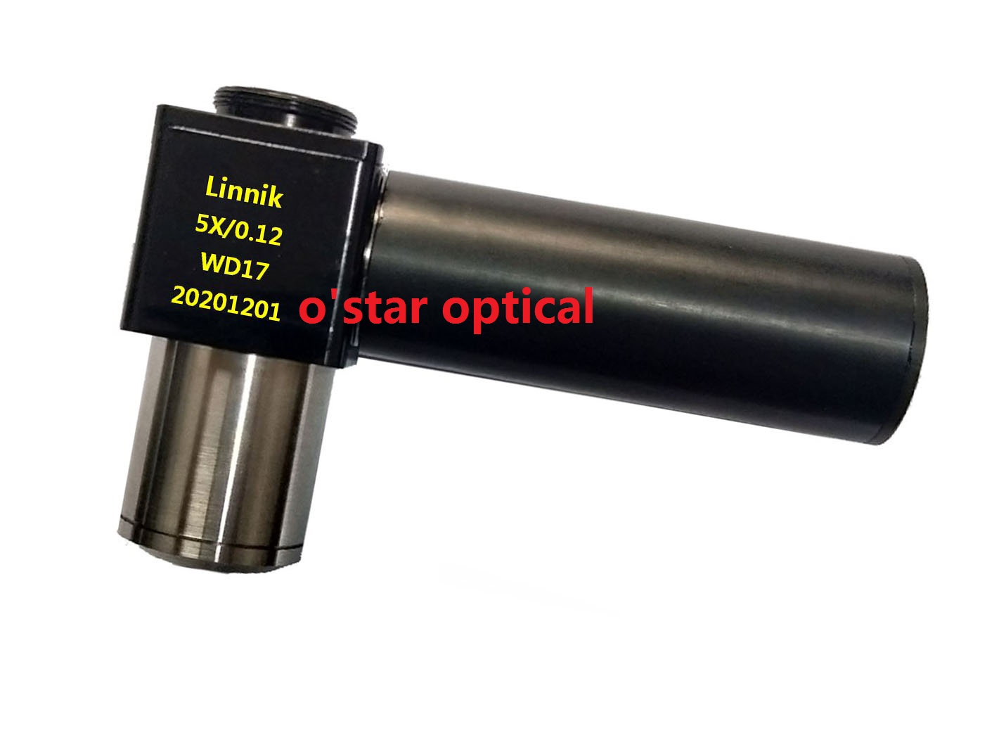
5X white light interference objective used
Test environment:
The workbench where the CR-100V white light interferometry system is placed is not vibration-proof, and external vibrations affect the measurement.
During measurement, three positions are selected as test areas. The substrate of the multi-groove glass plate is glass, with a reflectivity of about 4%.
Interference image
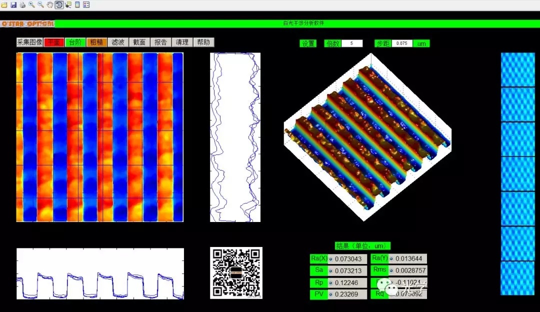
Software running interface
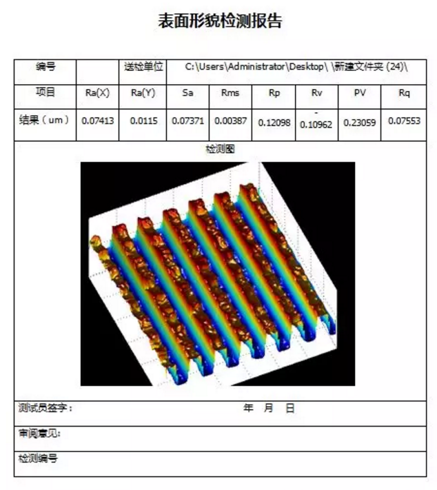
Measurement result at the first position
Measurement result at the first position (unit: um): The roughness of the 3D topography is represented by Sa, while Rp, Rv, PV (RZ), and Rq are analyzed within the entire image range. This evaluation method differs from the linear-direction measurement results of the roughness tester.
Ra(X)=0.07413,Sa=0.07371,Rp=0.12098,Rv=-0.10962,PV(RZ)=0.23059,Rq=0.07553,
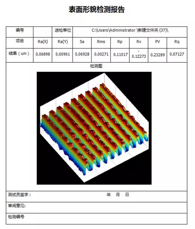
Measurement result at the second position
Measurement result at the second position (unit: um): The roughness of the 3D topography is represented by Sa, while Rp, Rv, PV (RZ), and Rq are analyzed within the entire image range. This evaluation method differs from the linear-direction measurement results of the roughness tester.
Ra(X)=0.06898,Sa=0.06928,Rp=0.11017,Rv=-0.12273,PV(RZ)=0.23289,Rq=0.07127,
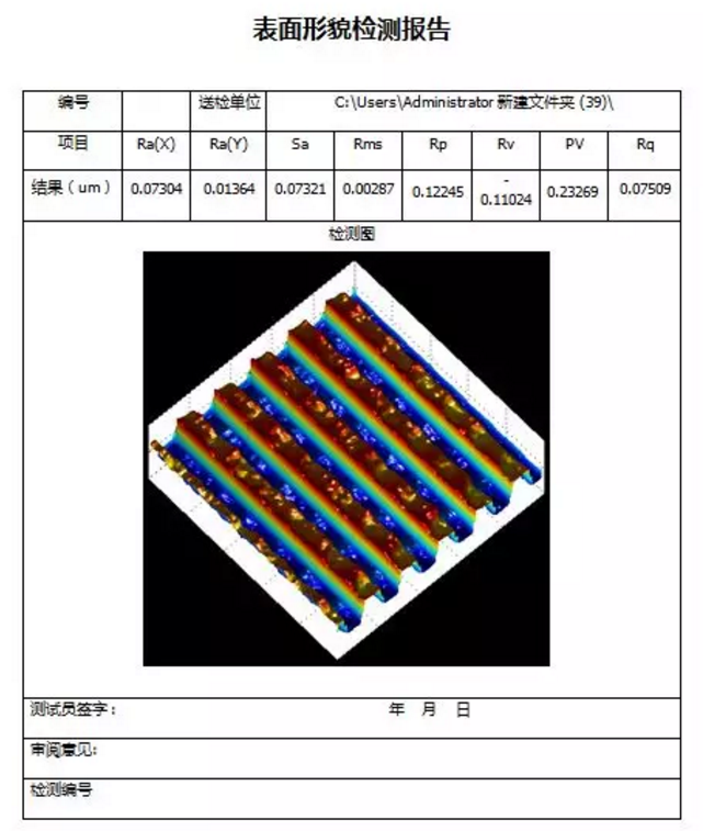
Measurement result at the third position
Measurement result at the third position (unit: um): The roughness of the 3D topography is represented by Sa, while Rp, Rv, PV (RZ), and Rq are analyzed within the entire image range. This evaluation method differs from the linear-direction measurement results of the roughness tester.
Ra(X)=0.07304,Sa=0.07321,Rp=0.12245,Rv=-0.11024,PV(RZ)=0.23269,Rq=0.07509,
White light interferometry measures the entire field of view, while the roughness tester measures roughness along a specific linear direction. Sa measures roughness over the entire field of view, and Ra(X) measures roughness along the roughness direction. Sa can be compared with Ra, but Sa has higher accuracy than Ra.
Analysis: After measuring the three positions,
(1):Ra(X)=0.07413,Sa=0.07371,Rp=0.12098,Rv=-0.10962,PV=0.23059,Rq=0.07553,
(2):Ra(X)=0.06898,Sa=0.06928,Rp=0.11017,Rv=-0.12273,PV=0.23289,Rq=0.07127,
(3):Ra(X)=0.07304,Sa=0.07321,Rp=0.12245,Rv=-0.1102,PV=0.23269,Rq=0.07509,
Roughness tester measurement results:
Ra=0.07,Rp=0.143,Rv=0.108,Rz=0.251,Rq=0.077,
Range of max and min values obtained: error interval of the result distribution.
Ra:0.00515,Sa:0.00443,PV(Rz):0.0023,Rq:0.00426
Comparison items with the standard block are Ra and Sa. The errors are:
(1):Ra(X):0.00413,Sa:0.00371,
(2):Ra(X):-0.00002,Sa:-0.00072,
(3):Ra(X):0.00304,Sa:0.00321,
The measurement results at the three points, roughness Ra, Ra(X), and Sa, compared with the results measured by the roughness tester on the standard block, show errors within 4 nm. Considering the environmental vibration, 4 nm is within the allowable error range.


 QQ客服1
QQ客服1